
- Details
- Last Updated: 03 October 2014
- Created: 21 February 2014
So... the plan mannnnn....
After a bunch of consideration and chatting with my techie friends at coffee (no i don't drink coffee, but we meet in a coffee shop).... the plan formed.
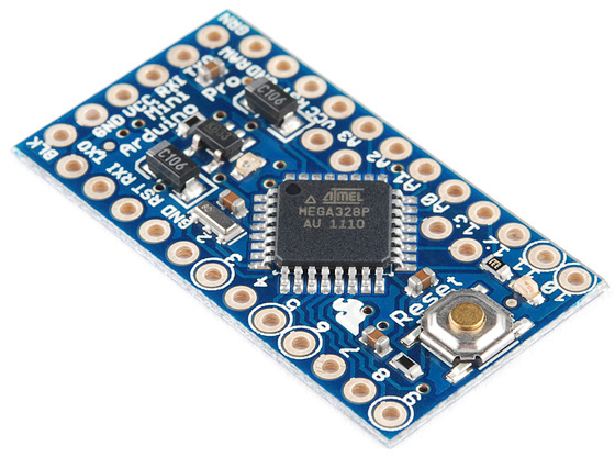
Of course each element would be turned on/off by a solid state relay. The relay in turn would be controlled by some sort of micro controller. I've been working with Atmel embedded CPUs since 2002 or so. Atmel, some of you may recognize is the cpu of choice for the Arduino series of boards and gadgets. Specifically the Atmega328.
I was soon paging through various electronics sites, and settled upon a Arduino Mini Pro. I really wanted to stay away from creating a custom board, and this was a nice compact design. I wanted the controller to be small enough to replace one control knob, including display and controls. This seemed to fit the bill.
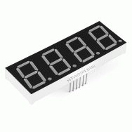
I continued to browse looking through displays and found a nice 4 digit 7 segment display, and some switches.
The controller would fit behind the display and had enough room to add SMD resistors directly from the board to the display leads. The controller had plenty of pins left over.
The controllers would be all connected together to get power, and communicate with each other and a central computer. As far as the control loop was concerned they'd be independent, but with two possible sources of user input. The first was up/down buttons on each controller, and the second via the communications line (a sort of simple multi-drop async protocol i've used before).
That communications line would be connected to a Raspberry Pi, with some sort of attached touch screen, as well as a web interface, forming a high-level GUI and Status display.
My thoughts next turned to fail safe issues. My research on solid state relays showed that the most common failure mode is to fail in the "on" state. One of my coffee and tech buddies who knows alot about appliances, said I should individually fuse each element, which sounds good. However I thought more was needed. I really didn't relish the thought of an element being on for a long period.
The plan developed to include a mechanical relay in the front end, held closed by another controller, which would be monitoring optisolators each connected to each elements power (appropriately resistor dropped of course). It will act as a watchdog. Since the elements will be on/off cycled at some slow rate, with the duty cycle determining the heat, there will always be an off time (even though it might be brief). Simple enough for a watchdog controller to deal with, and cut power if some element stayed on for too long (the definition of too long, has yet to be determined).
I've proceeded to order parts, and wire, and a few other odds and ends that should help the project along.